Installation and Assembly
The WP500 station is designed to be modular and versatile, consisting of individual modules that snap onto a DIN rail. Here’s a detailed guide to setting up the hardware for your WP500 system:
Components of the WP500 Station
|
Components |
Description |
|
DIN Rail |
The DIN rail is a standard metal rail used for mounting various electrical components. The WP500 modules are designed to snap onto this rail securely. Ensure that the DIN rail is properly mounted in the desired location, following the manufacturer's guidelines. |
|
WP500 Modules |
Ensure the WP500 is securely attached to the DIN rail and connected to the necessary power and communication interfaces. |
|
Power Supply (24V) |
The WP500 system requires a 24V power supply. Connect the power supply to the controller and any other modules that require power. Verify that the power supply is properly rated for the WP500 system and that all connections are secure. |
|
Ethernet Cable or Modem |
For internet connectivity, connect an Ethernet cable to the WP500 station for a LAN connection or use a modem if needed. This connection enables network communication and remote access to the WP500 system. |
Setup Instructions:
|
Sr. No. |
Field |
Description |
|
1. |
Mount the DIN Rail |
Install the DIN rail in the desired location using appropriate mounting hardware. |
|
2. |
Attach WP500 Modules |
Snap the WP500 modules onto the DIN rail. Ensure each module is securely attached and properly aligned. |
|
3. |
Connect the Power Supply |
Connect the 24V power supply to the power input terminals of the WP500 controller and other relevant modules. Check all connections for proper fit and secure attachment. |
|
4. |
Establish Network Connection |
Connect the Ethernet cable to the network port on the WP500 controller. If using a modem, follow the manufacturer's instructions for setup and connection. |
|
5. |
Verify Setup |
Check all connections, ensure the power supply is functioning correctly, and verify that the network connection is established. Test the system to confirm that all modules are operating as expected. |
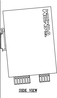
Side View:
|
NOTE: Damage to the contacts when tilting the modules Using a DIN rail with an installed height greater than 7.5 mm: If the height of the DIN rail exceeds 7.5 mm, this can lead to tilting of the modules when mounting or removing the modules. This may damage the contacts. • When using these DIN rails, make sure that the modules are perfectly perpendicular to the DIN rail when mounting or removing them. |
|
NOTE: Damage to electronics from the fixing elements Danger of malfunction If the fixing elements (screw, rivet, etc.) are too high, the bus base modules or the WP 500 are not correctly snapped onto the DIN rail. For fixing the DIN rail, only use elements with a maximum installation height of 3 mm. |
The distance between DIN rail fasteners must not exceed 200 mm. This distance is necessary for the stability of the rail when mounting and removing modules.
Mount the modules vertically on the DIN rail. As the module does not need to be tilted it provides easy installation and removal, even in confined spaces.
![]()
Recommended DIN rail spacing is 280 mm. This spacing allows room for wire duct to be installed without obstructing field wiring installation.