Diagnostic and status indicators
The WP500 modules are equipped with a range of diagnostic and status indicators designed to facilitate quick and effective error detection. These indicators provide visual cues about the operational state of the module and assist in identifying and localizing system or I/O errors.
Diagnostic Indicators
Diagnostic indicators on the WP500 modules are color-coded LEDs that offer insight into the module's condition:
|
Fields |
Description |
|
Green LEDs |
Indicate normal operation. If all green LEDs are on, the module is functioning correctly. |
|
Yellow LEDs |
Represent the status of the relevant input or output and the connected I/O device. |
|
Red LEDs |
Signal the presence of errors or faults within the module. |
Extended Diagnostics:
Some WP500 modules feature advanced diagnostic capabilities:
|
Fields |
Description |
|
Short Circuit or Overload Detection |
Modules can detect and report short circuits or overloads in the sensor supply. |
|
Individual Channel Diagnosis |
Certain output modules can diagnose each channel individually for short circuits. |
|
Supply Voltage Information |
Reports on supply voltage status are provided. |
|
Error Reporting |
Detailed information about I/O errors, including precise error types, is sent to the controller and displayed via status indicators. |
|
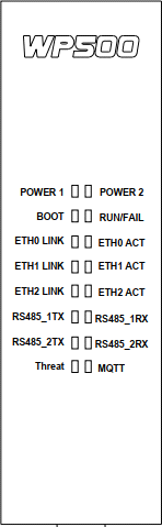
LED Indication-1 |
||
|
LEDs Name |
LED Indication |
Status |
|
POWER 1 |
Green |
Power Supply Given is OK |
|
RED |
Power Supply given in High Range (>30V) |
|
|
No Indication |
Power Supply given in Low Range (<10 V) |
|
|
POWER 2 |
Green |
Power Supply Given is OK |
|
RED |
Power Supply given in High Range (>30V) |
|
|
No Indication |
Power Supply given in Low Range (<10 V) |
|
|
BOOT |
Red |
Unit in BOOT Mode |
|
No Indication |
Unit in RUN Mode |
|
|
RUN/FAIL |
Green |
Unit is in RUN Mode |
|
Red |
Unit is in Fail |
|
|
ETH0 LINK |
Green |
Link Established |
|
ETH0 ACT |
Yellow |
Activity Established |
|
ETH1 LINK |
Green |
Link Established |
|
LED Indication-2 |
||
|
LEDs Name |
LED Indication |
Status |
|
ETH1 ACT |
Yellow |
Activity Established |
|
ETH2 LINK |
Green |
Link Established |
|
ETH2 ACT |
Yellow |
Activity Established |
|
RS485_1TX |
Green |
Data Transmit Active |
|
RS485_1RX |
Yellow |
Data Receive Active |
|
RS485_2TX |
Green |
Data Transmit Active |
|
RS485_2RX |
Yellow |
Data Receive Active |
|
THREAT |
No Indication |
Threat Detection Disabled |
|
Green |
Threat Detection Enabled, No Threat Received |
|
|
Red, Blinking |
Threat, Unacknowledged. |
|
|
Red, Solid |
Threat, Acknowledged. |
|
|
MQTT |
No Indication |
No MQTT Configuration |
|
Red |
MQTT Configuration Available, But Faulted |
|
|
Green |
MQTT Configuration Available, Healthy |
|