MODBUS networking
The Runtime Service includes fully integrated MODBUS master and slave functions for enabling MODBUS communication on serial link or ETHERNET.
Protocol specification
The following protocols are supported:
- MODBUS-RTU on a serial link.
- Open MODBUS on ETHERNET.
The following MODBUS function codes are supported:
|
MODBUS function code |
Description |
|
1 |
read coils |
|
2 |
read bit inputs |
|
3 |
read holding registers |
|
4 |
read input registers |
|
5 |
write 1 coil |
|
6 |
write 1 register |
|
15 |
write N coils |
|
16 |
write N registers |
As a default, the first valid address for each kind of data is 1. If you use MODBUS devices with other addressing conventions, you can change the base offset for each kind of data using the Tools / Addresses menu command.
Architecture
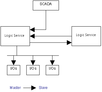
The Runtime Service can be used either as a server (MODBUS slave) or as a client (MODBUS master). Both server and client may be active at the same time. This allows multiple applications such as:
- Slave connection to a MODBUS master such as a SCADA system.
- Master connection to pilot MODBUS I/Os.
- T5 to T5 communication for real time exchange of variables (binding).
The configuration of slave and master functions is done in the Workbench Studio. Any data used by MODBUS is fully integrated in the application code and the VM database.
Communication ports
The client side opens a new port (RS or ETHERNET) for each configured MODBUS port.
Maximum number of COM Port connections depends on the used OEM. The Modbus Master driver supports 16 COM ports. Refer to the corresponding OEM instructions for further information.
On the server side, the management of low level communication (sending and receiving frames) is fully included in the T5 communication server, sharing the same ports for MODBUS requests and native requests. Thus the number of possible connected MODBUS maters fits the limitation of the communication server:
- One serial port
- Several ports on ETHERNET (platform dependent - generally 7 ports max).
Other slave ports can be open by calling MBSlaveRTU or MBSlaveUDP function blocks.
Note that the same port can be freely used either for communication with a MODBUS master or for dialog with the Workbench Studio. Both Workbench Studio and MODBUS frames are recognized by the communication server.
The MODBUS-TCP Server always used the configuration of the first port.
Data exchange - configuration
The Runtime Service manages a intermediate variable map representing MODBUS data, for both master and slave connections. A dedicated configuration tool is integrated in the Workbench Studio. Run it using the File / Open / Fieldbus Configuration menu command from the main window.
The MODBUS configuration is represented as a tree:
- MODBUS Configuration
- Slave (variables that can be accessed from external MODBUS masters)
- Input bits data block (read by masters)
- Variable (*)
- Input words data block (read by masters)
- Variable (*)
- Coil bits data block (forced by masters)
- Variable (*)
- Holding bits data block (forced by masters)
- Variable (*)
- Master communication port (connected to external MODBUS slaves) (*)
- Data block (read or write / bits or words) (*)
- exchanged Variable (*)
- Command variable (*)
- Status variable (*)
(*) The items with this mark can appear several times in the configuration.
MODBUS Slave configuration
You need to configurate the MODBUS slave in order to make variables visible from external MODBUS masters such as SCADA systems. Below is a simple example of slave configuration:
|
|
|
|
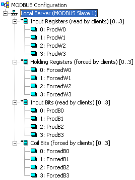
Double-click on the Local Server item to setup the MODBUS slave number that will identify the Runtime Service application. When the local server is selected, use the Edit / New data block menu command to insert MODBUS data blocks. The following kinds of block are available:
- input bits: bits read by external masters (function 2).
- coil bits: bits forced by by external masters (function 5 or 15).
- input registers: words read by external masters (function 4).
- holding registers: words forced by external masters (function 6 or 16).
Each data block is identified by a MODBUS base address and a number of items (bits or words).
|
|
|
Read and write requests sent by MODBUS masters will be denied if the range specified in the request does not fit within a data block defined in the configuration. Requests overlapping two data blocks will be denied. |
When a server data block is selected, use the Edit / New variable command to map a variable to an item of the data block. Each variable is identified by a valid symbol of a variable in the open project and an offset in the data block according to MODBUS addressing.For exchanging boolean variables through MODBUS words, a hexadecimal mask is available in order to define to which bit of a word a variable is attached. For example, enter the mask "0001" to map a boolean variable to the less significant bit of a word. For exchanging 32 bit variables (DINT, REAL...), you can select to map the variable on two consecutive words.
At any time you can sort the variables of each data block according to their offset using the Edit / Sort symbols menu command.
|
|
|
The creation of Modbus slave blocks requires especially register blocks like "Read Holding Registers". This block has a maximum length of 65535 bytes, what corresponds to 32767 registers. To have a larger address range than up to 32768 create a second block for the same function (e.g. Holding Register) . Example: To realize a Holding Register for the whole range of Modbus (max address: 65534), the following settings are required:
|
MODBUS Master configuration
You need to configurate MODBUS master ports in order to drive external MODBUS I/Os with variables. Below is a simple example of master configuration with just one port defined:
|
|
|
|
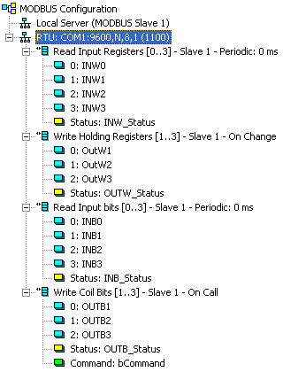
Run the Edit / New port to create a MODBUS port. Each port corresponds to one logical or physical MODBUS network. A port is based on either serial link or ETHERNET network. For ETHERNET ports, you must enter the IP address of the slave and its ETHERNET port number (usually 502). For serial ports, you must enter the settings of the port, according to your target platform conventions (e.g. "COM1:9600,N,8,1" on a PC based platform). As an option, you can select that the master retrys to open the port each time the communication fails.
|
|
|
Another option at the "port" level enables the management by the MODBUS stack of diagnostic counters for each slave. See below the list of possible status information you can map to variables.
When a port is selected, you can add new MODBUS data blocks by running the Edit / New data block menu command.
The following types of blocks are available:
- Read input bits (function 2).
- Read coil bits (function 1).
- Write coil bits (function 5 or 15).
- Read input registers (function 4).
- Read holding registers (function 3).
- Write holding registers (function 6 or 16).
Each data block is identified by a MODBUS slave number, a base address and a number of items (bits or words). The number of items is limited by MODBUS (2000 bits read, 1968 bits forced, 125 words read or 120 words forced).
For each request, you must define a timeout value in milliseconds, and an activation mode. Possible activation mode are:
- Periodic: you must then enter the minimum period.
- On change: in case of a write request, means that the request is changed each time a variable changes.
- On call: the request is activated using a variable.
For periodic requests, you must specify an alternate period to be used if the last exchange of the request has failed. This is typically used to slow down exchanges with faulty slaves.
When a server data block is selected, use the Edit / New variable command to map a variable to an item of the data block. Each variable is identified by a valid symbol of a variable in the open project and an offset in the data block according to MODBUS addressing.
For exchanging boolean variables through MODBUS words, a hexadecimal mask is available in order to define to which bit of a word a variable is attached. For example, enter the mask "0001" to map a boolean variable to the less significant bit of a word. For exchanging 32 bit variables (DINT, REAL...), you can select to map the variable on two consecutive words.
At any time you can sort the variables of each data block according to their offset using the Edit / Sort symbols menu command.
Status and command variables
When you map a variable to a data block in a master configuration, you can select it to be:
- An exchange of data (exchange between the MODBUS map and the T5 variables).
- A status (diagnostic information provided to the application).
- A command (using a variable for driving the stack).
Below are possible diagnostic and status information available:
|
Information |
Description |
|
Error report |
The variable is set to an error value when the last unsuccessful exchange is performed on the request. It is reset to 0 on the next successful exchange. |
|
Error report (set only) |
Same as upper, but the variable is not reset by the MODBUS stack. The application is in charge of resetting the variable. |
|
On-going request |
The variable is set to 1 when the request is sent to the slave and reset to 0 after either an answer from the slave or a timeout. |
|
Success counter |
The variable is increased each time the request is exchanged successfully. |
|
Fail counter |
The variable is increased each time the exchange of the request leads to an error. |
|
Retry counter |
The variable is set to 0 on the first trial and increased each time the request is retried. |
|
Slave: last error |
The variable contains the error code of the last error detected on this slave. |
|
Slave: last error date stamp |
The variable contains the date stamp of the last error detected on this slave. |
|
Slave: last error time stamp |
The variable contains the time stamp of the last error detected on this slave. |
|
Slave: last reset date stamp |
The variable contains the date stamp of the last "reset" action performed on slave counters. |
|
Slave: last reset time stamp |
The variable contains the time stamp of the last "reset" action performed on slave counters. |
|
Slave: transaction counter |
The variable is increased on any new exchange performed with this slave, whatever the exchange is successful or faulty. |
|
Slave: failed transaction counter |
This variable is increased on any new faulty exchange with this slave. |
Below are the possible commands you can map:
|
Command |
Description |
|
Command (enable) |
The request is sent continuously as long as the mapped command variable is TRUE (or not zero). |
|
Command (one shot) |
The request is sent only once when the mapped command variable becomes TRUE (or not zero). The variable is reset to 0 after the exchange. |
|
Reset counters |
The request counters are reset to 0 when the variable becomes TRUE (or not zero), and the command variable is then reset to 0. |
|
Slave: reset counters |
The slave counters are reset to 0 when the variable becomes TRUE (or not zero), and the command variable is then reset to 0. |
Below are possible error codes for "status" variables:
|
Error code |
Meaning |
|
0 |
OK |
|
1 |
MODBUS function not supported. |
|
2 |
Invalid MODBUS address. |
|
3 |
Invalid MODBUS value. |
|
4 |
MODBUS server failure. |
|
6 |
Server is busy. |
|
8 |
Data parity error. |
|
10 |
Invalid gateway path. |
|
11 |
Gateway target failed. |
|
128 |
Communication timeout. |
|
129 |
Bad CRC16. |
|
130 |
RS232 communication error. |
When you map a variable to a data block in a master configuration, you can select it to be a command. In that case, the data block is exchanged only when the variable is TRUE (or non zero for numerical data types).
Data types
You can freely map a variable of any data type to a MODBUS item. The Runtime Service automatically converts the value to the type of the variable.
For exchanging boolean variables through MODBUS words, a hexadecimal mask is available in order to define to which bit of a word a variable is attached. For example, enter the mask "0001" to map a boolean variable to the less significant bit of a word. For exchanging 32 bit variables (DINT, REAL...), you can select to map the variable on two consecutive words.
STRING variables are supported only if a "string" data format is specified. 64 bit variable (LINT and LREAL) cannot be extracted directly without lost of accuracy or data.
MODBUS networking |
|
IEC 61131-3 Automation platform > Drivers - Fieldbus configuration > MODBUS Master > Driver-specific information > MODBUS networking |
|
|
Created with the Personal Edition of HelpNDoc: Keep Your Sensitive PDFs Safe with These Easy Security Measures